Getting Started with NB|EASY
Table of content
Introduction
NB|EASY is a software tool developed to use Vodafone NB devices via PC.The NB device, connected via USB to PC, can be triggered to attach to the Vodafone NB-IoT network.
After successful connection establishment, the device is able to transmit and receive data via the NB-IoT network.
Version History
The following table shows the changes done with every NB|EASY documentation version:
| Version | Date | Changes |
|---|---|---|
| 1.4 |
| |
| 1.3 |
| |
| 1.2 |
| |
| 1.1 |
| |
| 1.0 |
|
Software Installation
Basic software requirements
- Java 8 runtime environment.
- NB-Vodafone driver (available in NB|EASY installation package, or as a stand alone version ).
Windows
- Use windows executable from the Software & Drivers for Vodafone LPWA Products to install NB | EASY software.
- The installer will take care of installing the Java environment and the required drivers.
- Start the program via desktop shortcut or start menu entry.
Linux
- The required UART driver has been distributed as part of Linux kernel since v4.4.132.
- Check whether the required kernel module is loaded:
lsmod | grep option. - Check whether you have read/write access to USB-UART bridge:
ls -la /dev/ttyUSB*.
Linux setup & troubleshooting
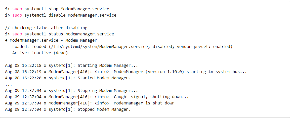
Currently, the ModemManager package (confirmed for version 1.10.0-1~ubuntu18.04.2) detects the R410 as a general QMI-WWAN modem and tries to configure it. Beside failing this task it blocks any "user" AT commands, e.g. using minicom.
The following shell commands stop and disable the ModemManager service:
Device Selection
After starting the application, the Device Selection tab is shown first. Here, the connected NB device can be selected.
- The Refresh button starts a new search for all USB-connected NB devices. An ongoing search is indicated by a progress bar below the button.
- After the search is finished, all available devices are displayed. By clicking on the device, it will be is selected for usage. After that, the Quick Start tab is shown.
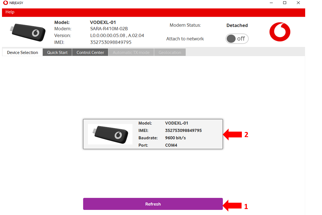
Figure 1: Device Selection tab
Quick Start
The Quick Start tab presents a simplified way to control the connected NB-IoT device.
Here, the device can be triggered to attach to the NB-IoT network and transmit sample data to the cloud.
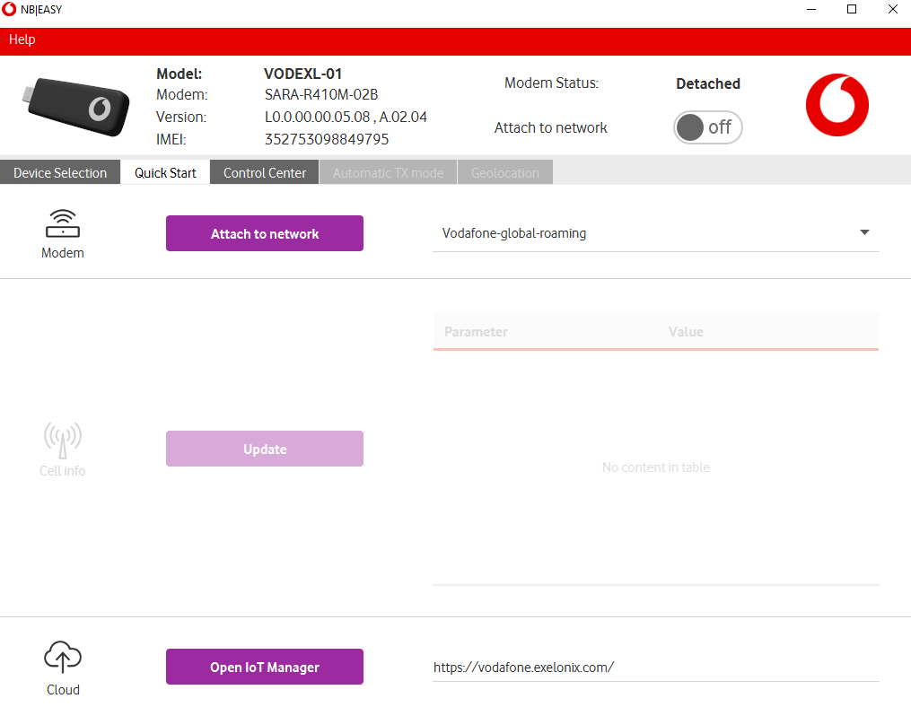
Figure 2: Quick Start tab
Device State
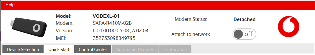
Figure 3 : Device State description
The top area of the application shows the selected device and its current state. It contains the following information:
- Device specific parameters:
- Name of selected NB-IoT device
- Modem type number
- Modem version, application version
- IMEI: International mobile equipment identity.
- Modem Status: shows the current status of the device.
- Attach to network button: triggers an attach or detach depending on modem status.
Modem Status
The modem status indicates the following values:
Modem Status | Description |
|---|---|
| Detached | The modem is powered on but not attached to the network. |
| Attaching | The modem is currently trying to attach to the network. |
| Attached | The modem is attached to the network |
| Detaching | The modem is currently detaching from the network. |
| Transmitting | The modem is transmitting data. |
| Receiving | The modem is receiving data. |
Table 1: Modem Status description
Detached
In the detached state, the device is not able to transmit data to the NB-IoT network. First, an attach procedure needs to be triggered, including the following steps:
- Select the NB-IoT network in the drop down menu.
- Click on the Attach to network button to start the attachment procedure to the selected NB-IoT network
Note: Be aware that the embedded SIM card requires either "Vodafone-global-roaming", a Vodafone Profile or a Vodafone partner profile, to be selected, otherwise the attach procedure will fail.
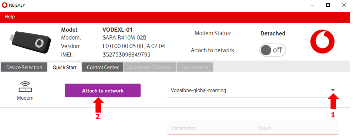
Figure 5 : Detached state description
Attached
In the attached state, the device is now able to transmit data to the NB-IoT network by the following control elements:
- Text field: to enter text to be transmitted when button (2 in figure 6) is pressed.
- Transmit to Cloud button: to start transmission to the cloud of the entered text (1 in figure 6) as well as the current cell information.
- Update button: to start a cell information update.
- Cell information list: which shows all received cell information of the last successful cell information update (see Displayed parameters in figure 8 below).
- Open IoT Manager button: to open IoT Manager website to view all successfully transmitted values as described in figure 7.
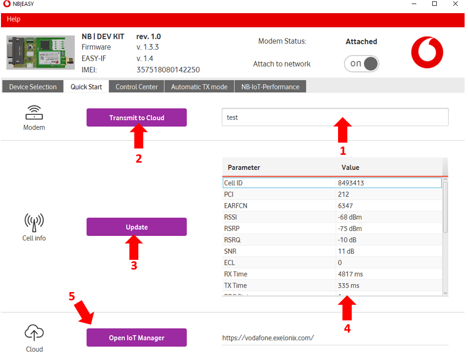
Figure 6 : Attached state description
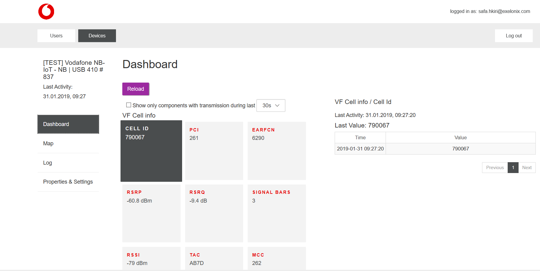
Figure 7: IoT Manager web site
| Parameter | Example Value | Acceptable range |
|---|---|---|
RSSI | -67 dBm | -113 dBm..-51dBm |
| PCI | 212 | |
| EARFCN | 6374 | 0..65535 |
| RSRP | -76.40 dBm | -140dBm..-44dBm |
| RSRQ | -3.00 dB | -3dBm..-19.5 dBm |
| Cell ID | 819965 | 0..(228 − 1) i |
| TAC | AB7D | |
| MCC | 262 | consists on 3 decimal digits |
| MNC | 02 | consists on 2 or 3 decimal digits |
| Signal bars | 4 | 0..5 |
| Assigned T3412 | 4 h | 0..35712000 sec |
| Assigned T3324 | 6 s | 0..11160 sec |
| Requested T3412 | 4 h | 0..35712000 sec |
| Requested T3324 | 1 h 40 m | 0..11160 sec |
Table 2: Displayed network parameters
Control Center
The control center is a advanced and detailed view of the communication between NB|EASY and the connected device.
Here, the user can monitor the message flow between NB-IoT device and NB|Easy and send individual messages to the device.
Important control elements are:
- Switch between "AT" and "Easy" mode (The USB connect LPWA does only support the "AT" mode)
- Message log: tracks the message history between NB|Easy and the connected device
- Clear message log (2 in figure 9)
- Save the current message log in a text file.
- Select supported AT command which could be send to NB-IoT device.
- Copy selected AT command to message text field (8 in figure 9 ).
- Message text field: The message to be sent to the device can be edited further.
- Send current AT command (8 in figure 9) to device.
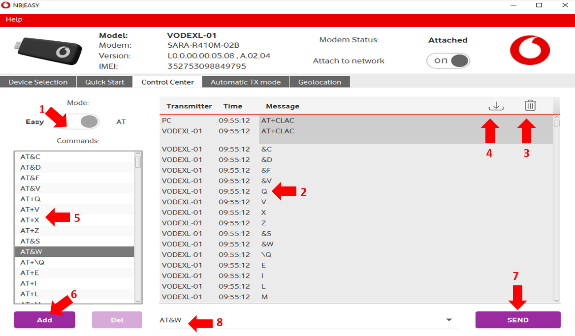
Figure 9: Control center tab
Automatic TX mode
In the automatic TX mode tab, NB|Easy can be configured to continuously send data packets to the cloud via the NB-IoT device. The data transmission interval can be configured.
The transmission status is displayed in Tab 1 and the sent data can be verified on the cloud. (see figure 7 above )
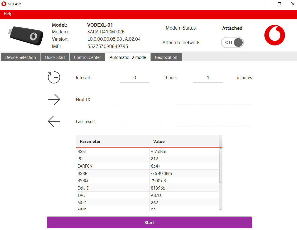
Figure 10: Automatic TX mode
Geolocation
This tab allows the user to display the current location parameters of the NB device ( Latitude,Longitude,Accuracy). It uses the characteristics of nearby Wi-Fi hotspots to discover where the host computer is located.
The cell parameters displayed are detailed in the Table 2 above .
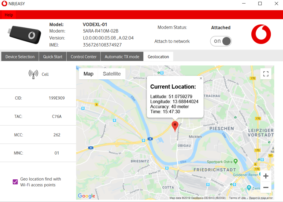
Figure 11: Geolocation tab
Annexe
| Parameter | Description | Definition | Example Value | Acceptable Range |
|---|---|---|---|---|
| RSSI | Received Signal Strength Indicator | RSSI is a measurement of the power present in a received radio signal | -67 dBm | -113 dBm..-51dBm |
| PCI | Physical Cell Identidy | PCI is an identification of a cell at physical layer. It has similar role as Primary Scrambling Code of UMTS cell.This physical cell ID is determined by Primary Sync Signal and Secondary Sync Signal. | 212 | |
| EARFCN | E-UTRA Absolute Radio Frequency Channel Number | EARFCN is a unique number given to each radio channel within the frequency bands used by the network . It can be used to calculate the carrier frequency | 6374 | 0..65535 |
| RSRQ | Reference Signal Received Quality | RSRQ is a C/I type of measurement and it indicates the quality of the received reference signal. The RSRQ measurement provides additional information when RSRP is not sufficient to make a reliable handover or cell reselection decision. | -3 dBm | -3..-19.5dBm |
| RSRP | Reference Signal Received Power | RSRP is the average power of Resource Elements that carry cell specific Reference Signals over the entire bandwidth. It is the average received power of a single RS resource element. | -76.4 dBm | -140 dBm..-44 dBm |
| TAC | Type Allocation Code | TAC is the initial eight-digit portion of the 15-digit IMEI and 16-digit IMEISV codes used to uniquely identify wireless devices. | AB7D | |
| MCC | Mobile Country Code | MCC consists of three decimal digit and it is used to identify the country. The first digit identifies the geographic region . | 262 | consists on 3 decimal digits |
| MNC | Mobile Network Code | MNC identifies the home PLMN of the mobile subscriber. The length of the MNC (two or three digits) depends on the value of the MCC. | 02 | consists on 2 or 3 decimal digits |
| Assigned T3412 | Assigned Timer 3412 | The periodic tracking area update timer to periodically notify the availability of the UE to the network. The procedure is controlled in the UE by (timer T3412). The value of timer T3412 is sent by the network to the UE in the ATTACH ACCEPT message and can be sent in the TRACKING AREA UPDATE ACCEPT message. The UE shall apply this value in all tracking areas of the list of tracking areas assigned to the UE, until a new value is received. | 4h | 0..35712000 sec |
| Assigned T3324 | Assigned Timer 3324 | The T3324 active timer determines the duration during which the device remains reachable for mobile terminated transaction on transition from connected to idle mode. The device starts the active timer when it moves from connected to idle mode and when the active timer expires, the device moves to Power Saving Mode | 6s | 0..11160 sec |
Table 3: Parameters Description