...
...
...
...
...
...
| Table of Contents | ||
|---|---|---|
|
This section describes the hardware part of the product which details the information about the PCB , the internal antenna as well as the integration part
...
current Version: v83 (06.11.19)
General Information
Name | Vodafone USB Connect LPWA |
|---|---|
Model | VODEXL-01 |
Manufacturer | Exelonix GmbH Washingtonstrasse 16/16a , 01139 Dresden Germany |
Description
The USB Connect LPWA is a USB-Device for cellular machine type communication and supports the cellular 3GPP LPWA-standards NB-IoT and CAT-M1 (LPWA - Low Power Wide Area)
...
The status is indicated by LED:
RED: Device is powered on
GREEN: device is registered to the network
GREEN/RED alternating: device is registered to the network and roaming (this will be the usual pattern)
Remark: The LED can be configured differently with a different GPIO configuration of the ublox R410 Module via AT-commands (see AT Comand cookbook)
...
Figure 1: USB connect LPWA Device
...
Figure 2: USB connect LPWA Device Bottom view / Top view
Physical Dimensions
...
Figure 3: Physical Dimension
...
IP Rating: IP40 (protected against Solid particles >1 mm, no Liquid ingress protection)
Printed Circuit Board
...
...
Figure 4: General USB layout
External Interfaces
The device has two interfaces:
USB-A (male)
TS9 RF-interface for external antenna
USB
The USB connector provides power and data-interface with host devices (e.g. Laptop, Raspberry Pi, SBC, ...).
The connection is specified as defined by the USB standard.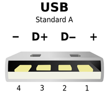
...
Figure 5: USB-A connector (male)
PIN | Description |
|---|---|
1 | VCC (5V) |
2/3 | Differential data wires |
4 | GND |
Table 1: USB PIN Description
...
In order to connect an external antenna, the device has an TS9 connector (female).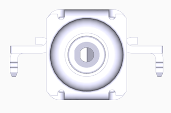
...
Figure 6: TS9 (female) external antenna connector
...
Examples for recommended external antennas:
Model, Link
...
Supported Frequency Bands
Following LTE-Frequencies are supported.
LTE Band | Range (MHz) | Uplink (MHz) | Downlink (MHz) |
|---|---|---|---|
12 | 700 | 699-716 | 729-746 |
13 | 700 | 777-787 | 746-756 |
28 | 700 | 758 - 803 | 703 - 748 |
20 | 800 | 832-862 | 791-821 |
5 | 850 | 824-849 | 869-894 |
8 | 900 | 880-915 | 925-960 |
2 | 1900 | 1850-1910 | 1930-1990 |
3 | 1800 | 1710-1785 | 1805-1880 |
4 | 1700 | 1710-1755 | 2110-2155 |
Table 2: LTE Frequency Bands
Internal Antenna Characteristics
...
Table 3 describes the working bands in LTE NB-IOT and LTE -Cat M1 that the USB connect LPWA supports.
LTE Band | Channel | Downlink (MHz) | TIS (dBm) | Channel | Uplink (MHz) | TRP (dBm) |
|---|---|---|---|---|---|---|
12 | 5095 | 737,5 | -105 | 23095 | 707,5 | 21,7 |
13 | 5230 | 751,0 | -106 | 23230 | 782,0 | 21,6 |
28 | 9435 | 780,5 | -102 | 27435 | 725,5 | 21,7 |
20 | 6300 | 806,0 | -99 | 24300 | 847 | 20,3 |
5 | 2525 | 881,5 | -102,9 | 20525 | 836,5 | 20,3 |
8 | 3625 | 942,5 | -112 | 21625 | 897,5 | 21,9 |
3 | 1575 | 1842,5 | -116 | 19575 | 1747,5 | 20,1 |
2 | 900 | 1960 | -114 | 18900 | 1880 | 21,7 |
4 | 2175 | 2132,5 | -112 | 20175 | 1732,5 | 21,3 |
Table 3: NB-IoT Antenna Performance
LTE Band | Channel | Downlink (MHz) | TIS (dBm) | Channel | Uplink (MHz) | TRP (dBm) |
|---|---|---|---|---|---|---|
12 | 5095 | 737,5 | -94,6 | 23095 | 707,5 | 20,8 |
13 | 5230 | 751,0 | -94,9 | 23230 | 782,0 | 22,4 |
28 | 9435 | 780,5 | -91,5 | 27435 | 725,5 | 22,6 |
20 | 6300 | 806,0 | -91,8 | 24300 | 847 | 21,6 |
5 | 2525 | 881,5 | -97,4 | 20525 | 836,5 | 20,7 |
8 | 3625 | 942,5 | -100,1 | 21625 | 897,5 | 22,2 |
3 | 1575 | 1842,5 | -107,0 | 19575 | 1747,5 | 20,4 |
2 | 900 | 1960 | -105,8 | 18900 | 1880 | 22,5 |
4 | 2175 | 2132,5 | -105,2 | 20175 | 1732,5 | 20,3 |
Table 4: Cat-M1 Antenna Performance
Integration USB Connect LPWA
Peripheral Layouts
For optimal antenna performance we recommend the use of the layouts detailed in the following figures. To avoid poor antenna performance an incorrect layout is also illustrated.
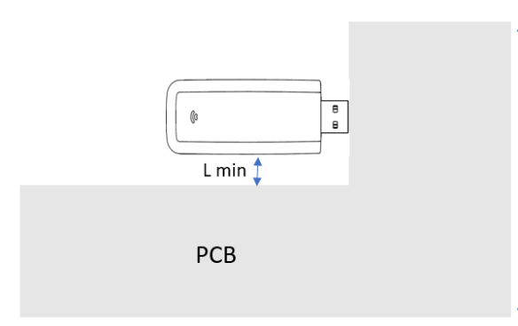
Recommended layout for low frequency bands bands (5, 8, 12, 13, 20, 28)
Lmin >2 cm: The minimum distance between the dongle and the PCB
The USB dongle is connected to a PCB min 10 cm* 10 cm (L*W)
Ensure that the dongle is not covered by any metal shielding (such as an earpiece or loudspeaker) unless recommended by the layout.
Optimum performance can only be achieved if any surrounding metal has a min distance of 2 cm to the dongle.
Maintain a distance between any other auxiliary devices and the dongle to avoid RF coupling.
Critical RF exposing device components such as a crystal oscillator and switched-mode power supply must be filtered or shielded to minimize potential impact on the dongle.
Do not place any components that interfere with antenna performance above the dongle's antenna to avoid a drop in antenna gain.
The USB dongle is embedded in the longer edge of the PCB, therefore the internal antenna for lower frequency bands is not blocked by the PCB.
...
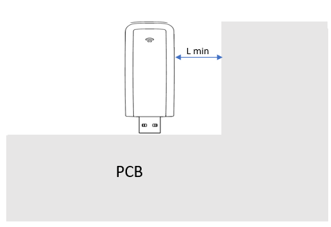
Recommended layout for high frequency bands (2,3,4)
The USB dongle is embedded in the longer edge of the PCB, therefore the internal antenna for higher frequency bands is not blocked by the PCB.
Not recommended layout
...
This set-up affects both internal antennas and therefore cannot achieve the optimum performance. For such conditions the use of an external antenna is recommended. If that is no option than the minimum gap of Lmin >2 cm between the dongle an PCB must be ensured.
Working and Storage Environment
Parameter | Minimum Value | Maximum Value | Unit | Remarks |
|---|---|---|---|---|
Normal operating | -20 | +65 | °C | fully functional and meet 3GPP / ETSI specifications |
Extended operating | -40 | +85 | °C | RF performance may be affected outside normal operating range, |
Storage temperature | -40 | +85 | °C | |
Humidity Range | 5 | 95 | % |
Table 5: Environmental Conditions
...
RF Tx/Rx data connection is in progress.The module is prepared to accept data signals from an external device.
Mode | Current Consumption Nb-IoT | Current Consumption Cat-M1 |
|---|---|---|
Deep-Sleep | 8 µA | 8 µA |
Active | 8 mA | 8 mA |
Connected | 60 mA (min TX-Power) 65 mA (0 dBm) 80 mA (12dBm) 100 mA (18dBm) 140 mA (max TX-Power) | 100 mA (min TX-Power) 105 mA (0 dBm) 125 mA (12dBm) 150 mA (18dBm) 190 mA (max TX-Power) |
Table 6: Module Module Current Consumption
RF Noise Considerations
For optimum performance of the device some RF-constraints need to be considered.
Noise from the Processor Board:
The processor board which the USB Connect LPWA is connected to may emit RF noise signals which results from the clocks of the processor as well as the data rate of digital interfaces such as USB. This RF noise may be received by the internal antenna of the USB Connect LPWA and therefore may limit your receive sensitivity. This may lead to a considerable lower RX-sensitivity in the down link. Therefore the following is recommended:
Ensure proper EMC-shielding of the processor board.
Use an external antenna placed outside the RF-noise area to improve RX-performance.
Noise from an active USB-Connection:
The USB-connection is a high speed data interface with a clock, which might also cause interfering RF-noise. The USB 2.0 clock noise shows up at multiples of 480 MHz since the the USB clock is 48 MHz * 10 = 480 MBit/s. This type of RF-noise is quite commonly seen at 480/960 MHz on USB powered wireless devices. This might affect performance of the USB Connect LPWA in the lower frequency bands.
Therefore the following is recommended:
Avoid long USB-Cables between the processor board and the device.
Ensure proper EMC-shielding of the USB-Connection.
Use an external antenna placed outside the RF-noise area to improve RX-performance.