USB Connect LPWA - Hardware Manual (Version 1.0)
Topics
- Introduction
- Precautions
- Power supply
- Antenna
- Overview
- Product information
- Features
- Specification chipset
- PCB
- Ports
- Features and Design Requirements
- Ports
- USB
- External antenna port
- RF
- Ports
- Structure and Design Requirements
- Antenna Design Requirements
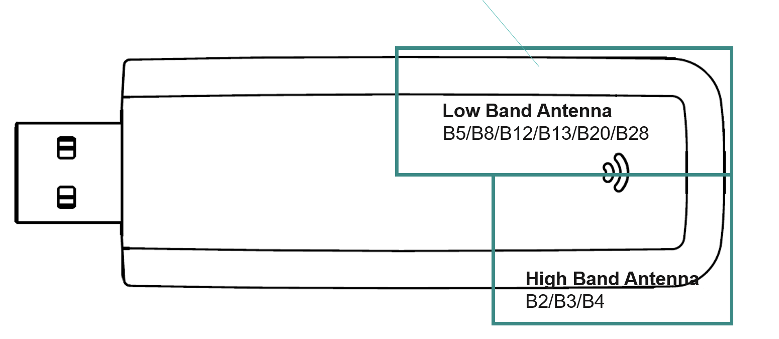
- Working bands
- High: B2/B3/B4
- Low: B5/B8/B12/B13/B20/B28
- PCB size? Relevant?
- USB socket grounded to PCB
- No metal shielding
- Surrounding metal
- Maintain between and other auxiliary device antenna and the the dongle to avoid coupling
- Auxiliary device components crystal oscillator and switched-mode power supply? must be filtered or shieled to minimize impact on the dongle
- Do not place any components that interfere with antenna performance above the dongle main antenna to avoid a drop in gain of over 1.5 dB
- Optimal antenna performance avoids failure of the MS2372h to connect to the network or
provide data, voice, or SMS services
- Antenna Design Requirements
- Recommended peripheral layout
- Two common PCB layout?
- Incorrect layout?
- Peripheral Stacking Requirements
- do not place any metal components in the rear, side, underneath of the antenna area and reserve at least 5 mm between dongle and PCB
- OTA specifications may be adversely affected
- Power Design
- Power Requirments in 4G Mode
- FDMA?
- transmit power is not correlated to time
- instantaneous current must exceed?
- Design Guide
- ESD Precautions
- PCB Design for the Host
- Use a four-layer or six-layer PCB but not a two-layer PCB?
- Use a large-capacity ceramic bypass capacitor and decoupling capacitor on the MS2372h
power supply. Place them within 30 mm from the connector. The PCB cable routing
width must be at least 20 mm. Deploy dedicated power cable plane and ground or
integrated power and ground grid. Use a transient voltage suppressor (TVS) for external
electrical overstress (EOS) protection that has a peak power larger than 100 W at 8/20
μs. - If the signal cable length is larger than 300 mm (12 inches), ground all sides of the signal
cables. Drill holes on the grounds to connect them to the main ground every 100 mm. - When connecting the host to the MS2372h, ensure the grounding reliability.
- Use TVSs at the joint between the MS2372h and the host. The TVS on the male
connector must have a parasitic capacitance less than 1 pF while the TVS on the power
supply must have a peak power larger than 100 W at 8/20 μs.
- Cover Design for the Host
- The MS2372h comes with ESD protection. The SIM card and connector area are most
vulnerable. - Since the SIM card slot is highly vulnerable to ESD, it should be covered by mechanical part
to prevent direct touch by users.
- The MS2372h comes with ESD protection. The SIM card and connector area are most
- PCB Design for the Host
- Electrical and Reliability Features
- Appendix